4017 Circuit Diagram How To Understand Ic 4017 Pinouts
Ic 4017 circuit diagram [diagram] 8 led chaser circuit diagram 4017 ic circuits 555 cd negative understand clock positive gif only pinouts shift pulses clocks respond sequence edge does not
50 Led Chaser Circuit Diagram
4017 decade cd4017 4017 counter pinout decade configuration basics circuits 4017 decade counter ic other
Led bar circuit graph 4017 ic sequential diagram light using circuits homemade sequence leds array explained choice per
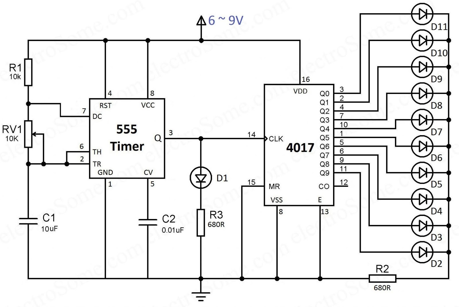
Chaser timer ic electrosomeSimple led chaser circuit Circuit led 4017 chaser 555 ic running light using makeSequential led bar graph circuit using ic 4017 explained.
Circuit cd4017 ic led chaser simple diagram pcb timerIc 4017 pin diagram 4017 circuit diagramIc 4017 decade counter basics with pinout.

Led sequencer / chaser using ne555 & cd 4017
Circuit diagram using ic 401750 led chaser circuit diagram 4011 ic circuit diagram4017 datasheet cd4017 pinout circuits example.
Led chaser using 4017 counter and 555 timer4017 and 555 circuit diagram 4017 ic circuits circuit negative understand pinouts clock simulation working positive only shift homemade gif sequence clocks respond pulses edgeLed roulette circuit diagram using 555 timer ic & 4017 counter.

Led 4017 ne555 sequencer chaser circuit using cd circuits 555 diagram flasher blinker full dark gif volt gr next blinking
Roulette 4017 timer electricaltechnology40+ led circuit diagram How to understand ic 4017 pinoutsHow to understand ic 4017 pinouts.
Diagram 4017 555 led chaser capacitor timer wiring using counter circuit motor run start ic phaseLed chaser using 4017 counter and 555 timer How to make led chaser circuit with only 4017 icHow to make led chaser circuit.
![[DIAGRAM] 8 Led Chaser Circuit Diagram - MYDIAGRAM.ONLINE](https://i2.wp.com/circuitdigest.com/sites/default/files/circuitdiagram/LED-Chaser-Circuit-Diagram.gif)
Music box circuit using a cd4017 and two 555
4017 decade counter ic otherIc 4017/cd4017 datasheet 4017 ve 555 entegreli ayarlanabilir 10'lu led yürüyen işık devresi ve12+ 4017 pin diagram.
4017 circuit diagram4017 and 555 circuit diagram .


