4 Bit Parity Generator Circuit Diagram [diagram] Circuit Dia
Parity generator diagram logic checker binary bit odd figure parallel table [solved] derive the circuit for a 3 bit parity generator with inputs a Bit parity help generator even problem solved need
Step by Step Method to Design a Combinational Circuit – VLSIFacts
3 bit parity generator [diagram] circuit diagram 3 bit parity generator Parity generator checker circuit
Implementing a binary parity generator and checker with greenpak
4‐bit parity generator (a) logic schematics,(b) qca architecture4-bit even parity generator 4‐bit parity generator simulation[diagram] circuit diagram 3 bit parity generator.
Parity checker logic circuit generator types odd diagrams itsCircuit design of parity generator – vlsifacts Solved design a 4-bit even parity checker as shown below.Circuit implementation of 4-bit even parity generator.

[diagram] circuit diagram 3 bit parity generator
8-bit parity generator circuit diagramParity generator and parity checker circuits Digital combinational circuitsSolution: solved design the circuit of a 2 bit parity generator and the.
Parity generator and parity checker[solved] design and build a 4-bit even parity generator and the 4-bit even parity generatorDesign a 4 bit odd parity generator.

8 bit even parity generator vhdl code
Design a 4 bit odd parity generatorStep by step method to design a combinational circuit – vlsifacts Figure 1 from 3-bit digital electro-optic odd parity generator based onCircuit diagram 3 bit parity generator.
Parity generator circuit even diagram spread wordParity odd checker technobyte The four-bit parity generator and checker circuitLogic diagram of 4-bit even parity generator.

4-bit even parity generator
Solved: chapter 4 problem 31p solutionParity generator and parity checker : logic circuits and their types Solved shown below is another design for a 4 bit parity8-bit parity generator circuit diagram.
Design a 4 bit odd parity generatorCircuit parity generator even combinational step method Logic circuit truth table generator8 bit parity generator circuit diagram.


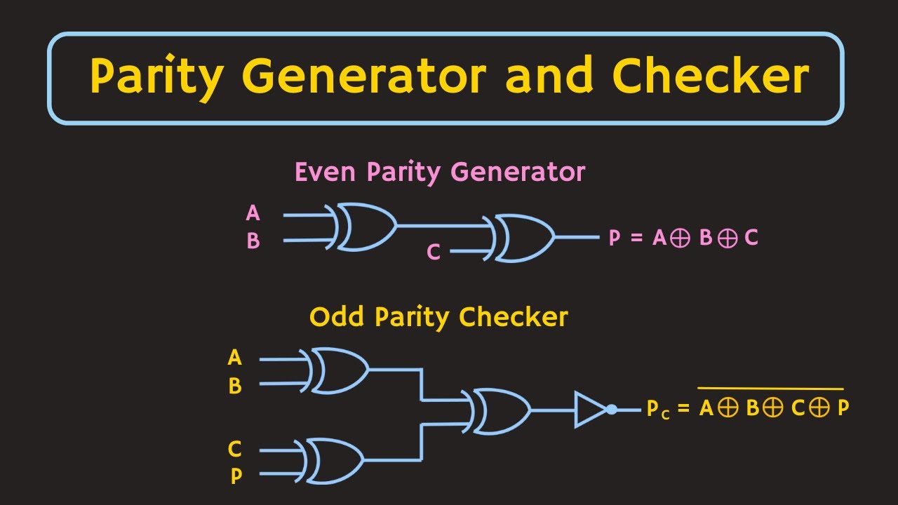
![[DIAGRAM] Circuit Diagram 3 Bit Parity Generator - MYDIAGRAM.ONLINE](https://i.ytimg.com/vi/YH--UwQaMhY/maxresdefault.jpg)


